PWM-Pulse width Modulation
- Hazem Assal

- Oct 22, 2021
- 2 min read
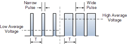
PWM or PDM (Pulse duration module) is a method of reducing the average power delivered by an electrical signal, by switching ON and OFF the voltage (¤t) to the load.
Advantage of using PWM:
Low power loss, high efficiency, easy to use, the circuit need a smaller area & low cost.

Application:
PWM work well with digital control to provide the duty cycle needed, it can also control analog devices with a digital output.
Some examples of where PWM can be used:
-Control Different types of motor (Stepper & Servo motors).
-Control the speed of a DC Motor.
-Signal modulation (Telecommunication), where the width of the pulse is corresponding to a specific data value encoded in one end and decoded to the other.
-Power delivery.
-Voltage regulation.
-Audio amplifications.
-Controlling analog signal.
Duty Cycle:
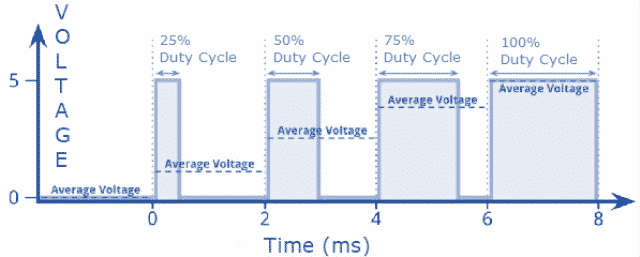
The duty cycle of the PWM signal refer to the ratio of the time that the signal is in a high state over the total time it take to finish one cycle.

EX: Suppose we want to control the speed of a 12V or 5V DC motor. The speed of the DC motor can be controlled by controlling the applied voltage, if we apply the PWM on the motor and vary the width of the pulses, the duty cycle also be varied and the average value will change according to the duty cycle, therefore, the speed will be changed according to the average value.


The frequency in Pulse Width Modulation technique has a very important role. The frequency is defined as the no. cycles per second. When we use PWM for dimming of light, then if we use high frequency we feel like that the light is not dimming, but if we use low frequency then we see the dimming of light very clearly.
There are different frequencies are used for different applications.
How to Generate PWM Signal:

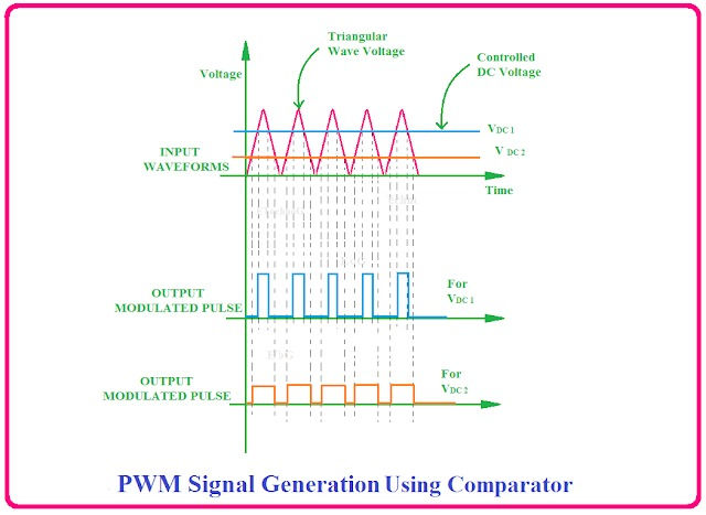
Using a comparator to compare the tooth wave signal to an input voltage.

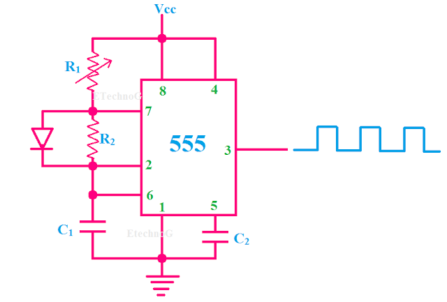
Generating PWM signal with IC555:
We can generate the PWM signal using IC 555 By varying the value of R1 we can control the duty cycle or width of the pulses.


Comments