
Line Follower Robot
- Mohamed Sami

- Sep 13, 2021
- 2 min read
Updated: Sep 26, 2021
The robot can follow the drawn line on the ground by detection the difference of reflecting light, where the line is black with a white ground vice versa.
The sensors of robot detect the black line on the white ground based on the black surfaces absorb the light and the whit surfaces reflect the light.
The following figure shows the all conditions of line follower robot

Condition (A): In this case the 2 sensors of robot detect the black line, so the robot goes forward.
Condition (B): The second sensor detects the black line and other detects the ground, so the robot rotates right to follow the black line.
Condition (C): The first sensor detects the black line and other detects the ground, so the robot rotates left to follow the black line.
Condition (D): The both sensors detect the ground, so the robot will stop.
We need to change all previous conditions to electronic signals that can move a robot in a certain direction according to a feedback signals from sensors.
Sensor-01 | Sensore-02 | Motor-01 Black Wire | Motor-01 Red Wire | Motor-02 Black Wire | Motor-02 Red Wire |
|---|---|---|---|---|---|
0 | 0 | 0 | 0 | 0 | 0 |
0 | 1 | 1 | 0 | 0 | 0 |
1 | 0 | 0 | 0 | 0 | 1 |
1 | 1 | 1 | 0 | 0 | 1 |
System Overview
the robot has many components to do his job starting from sensors to detect the line, Input signal conditioning that responsible for tuning the sensor signals and send it to the controller, Output signal conditioning which is send the commands from controller to the actuators, at the end selecting a proper type of actuators suitable with the application.

Sensors

We use laser & LDR sensor, where the laser is a source of light that light on the ground and the LDR detects the reflection light of laser beam, so it can detect the black line or white ground.
The LDR sensor detects the intensity of light by changing in its resistance.
The resistance of LDR = 1KΩ in the white ground, and it is equal 10KΩ with black line.
Input Signal Conditioning

The controller can’t understand the difference of resistance but it works digitally, so we need to convert the signal of LDR to be 0 or 1 to be valid with controller.
We make this condition by voltage divider circuit.
Vout = 2.5V Detecting white color
Vout = 0.4V Detecting black line
Controller
The controller is so simple and we can select it through the previous table
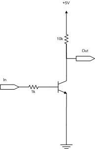
So we need a NOT logic gate to operate the Motor-01 and Motor-02.
the next figure shows how to make NOT gate using NPN transistor.
Output Signal Conditioning
The motors work with two relays and it needs a relay driver circuit to take a signal from controller and operate the motors.
The Figure shows the relay driver circuit using NPN transistror.
Simulation and Implementation
Build your circuit using PROTUES and simulate it, then make a layout PCB and do it.


Comments