
Straight Line Walking Mechanism
- Mohamed Sami

- Oct 5, 2021
- 1 min read
Updated: Jun 10, 2023
Brief

The walking mechanism depends on crank shaft and two links connected together with two sliding pivots.
This connection with a certain dimensions can easily convert the rotation motion in crank shaft to reciprocating movement to the link which is connected directly with crank shaft, then the movements transfer to the leg making a straight line motion path as shown.
By using two configurations of these linkages we can get a simple walking mechanism.
Conceptual Model

As shown in the figure, the model of walking mechanism depends on the rotation motion of crank shaft then the movements transfer to the foot through the linkage with (Fixed dimensions, and Variable dimensions).
Fixed Dimensions: the dimensions of the linkages and mechanism itself which does not change during movement [L, K, R, C, and y]
Variable Dimensions: which are change during movement [X, L2, a, b, L1, d, Theta, and Beta]
Mechanism Calculations
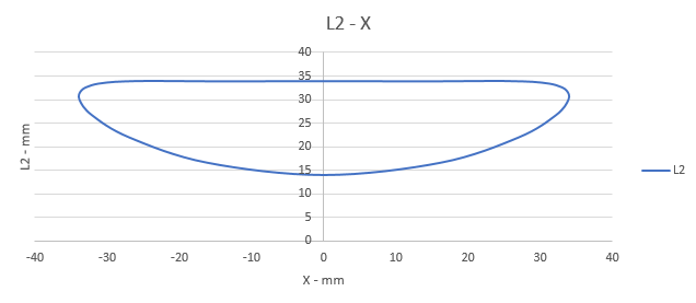
let's say the Input of mechanism is the angle of crank shaft (Theta), the output is (L2, and X) because the L2, and X are main parameters to draw the path.

Now it is become easy to use Microsoft Excel to draw the path profile of foot to be sure that is move in straight line.


This is a clear conceptual breakdown of how a crank shaft with two sliding pivots can translate rotation into reciprocating motion that drives the leg along a straight-line path. I appreciate the way you separate fixed dimensions from variable ones; it makes the mechanism’s degrees of freedom easier to reason about. If someone is trying to model or validate the kinematics data in practice, I’d also find it helpful to export computed coordinates using TableConvert with an excel to json workflow.
Hey this is great! Looks like it may be the solution for the walking of my giant dinosaur robot I'm working on! The link for the 3D model doesn't seem to work though. Could you please upload it somewhere else or email it to me if I send an eTransfer? My email is MarshallVisions@Outlook.com Thanks!