
How to design Gripper Part 2
- Ahmed Helwa
- Jan 1, 2022
- 3 min read

Introduction
In Part 1 of this series we have been exposed to gripper system architecture along with a guide for designing your own gripper starting from studying the grasped part until the gripper is developed.
In this part we will go through an actual case study of a gripper design.
Case Study Scope
The Scope of the case study is to design a gripper for a robot arm that is intended to pick and place chess parts.
In order to do that, we will follow the design guide described in Part1
Design Guide Steps
Stage 1: Study the part to be grasped and the task to be performed
• Generally, the chess parts are not fragile, not slippery, but are of different sizes and different shapes.
• dimensions in the below picture is in mm units.

• The parts weight range from 15 to 30g
• The Chess parts is going to be applied to the following forces:
1- The mass of the chess part (Computed)
2- The magnetic force with the board (factor of safety)
since there exist a magnet at the bottom of each part to hold it on the board
3- Robot arm acceleration during movement (factor of safety)
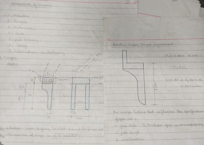
Force Analysis
Assumptions:
• Chess parts mass = 30g = 0.03Kg
• Assume Rubber Finger tip u = 0.1 ( taking into consideration that a rubber cover is going to exist around the fingers of the gripper)
• Safety Factor = 2 (to cover magnetic resistance and possible acceleration)

Sensory information needed:
• Micro limit switches are needed to know when the stop the gripper actuator at open and close actions
• FSR (Force sensitive resistor) is optionally used to measure how hard and how soft the robot arm is grasping the object
Stage 2: Determine additional requirements, not directly related to the act of acquiring and gripping parts
• The Chess parts are located adjacent to each other, which must be considered when the gripper is in open and closed position.
The part must be grasped without disordering the neighbor parts around that part position.

Stage3 : Determine Specific Solutions to the requirements in stage 1 and stage 2
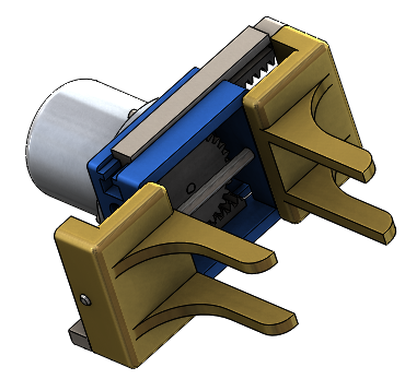
A parallel jaw gripper can be designed using different mechanism, for example, like the vice which is composed with stationary jaw and another movable jaw which is moved using power screw mechanism.
I chose to design a parallel jaw gripper with a rack and gear mechanism, this mechanism was chosen because of its flexibility and the location of the motor will be axial to the jaws, which will not defect the shape of the robot arm in general

Stage 4: Begin to design and develop combining the foregoing modular solution
In this part a complete design process is started to completely formulate the gripper by first visualizing the system through Free hand sketches,
Then a modelling and validation process is to take place in order to fully define the material and dimensions to be used of the racks, spur gear, motor, finger guide and fingers parts
The fingers was design in the form of hollow gripper jaw, a rubber sheet is mounted on top of the finger at the direction of the grasped object, this design will help in grasping different shapes of chess pieces, and the rubber will give damping and friction which will increase the grasping effectiveness and delicacy
Conclusion:
Stage 5 (Redesign part and/or the task) was not applicable in this project as the chess board and chess parts was a design constraints in the system.
That gripper was developed in real life and it worked efficiently as part of the chess playing robot project
In this part we have gone through a gripper design case study going following the design guide that was introduced in part1


Comments