How to design Robot Gripper Part1
- Ahmed Helwa
- Sep 29, 2021
- 2 min read
Updated: Nov 30, 2021
Introduction
In manufacturing industries, robots are generally used for many applications. The task the robots perform may involve assembling parts or fitting them into clamps and fixtures. These tasks place greater demands on the accuracy of the arm and also the gripper
Once a part has been picked up, it must be held securely and in such a way that the position and orientation remains accurately known with respect to the robot arm.
System Architecture

Gripper System is mainly comprised of 2 main functions as follows,
1- Gripping Mechanism
This is the mechanical system which is responsible of transforming the mechanical motion from the actuator to a open/close mechanism based on the Finger Configuration
2- Finger Configuration
The Finger configuration is mainly responsible for grasping objects.
Based on the geometry and nature of the object, the finger configuration can be comprised of 2 or more finger to provide the necessary hold.

Gripper Design
The tasks the robot performs may involve assembling parts or fitting them into clamps and fixtures. These tasks place greater demands on the accuracy of the arm and also the gripper.
Once a part has been picked up it must be held securely, it must be held securely and in such a way that the position and orientation remains accurately known with respect to the robot arm.
Force
Design Guide
Stage 1- Study the part to be grasped and the task to be performed
try to express the gripping requirements as abstractly as possible. This will require a force analysis.
It is also possible at this stage to decide whether contact forces must be distributed over large areas or not. Are the parts fragile? compliant? slippery? irregularly shaped?
The flexibility and compliance required from the gripper will depend on these characteristics and on task-related criteria.
Finally, what sort of sensory information is required from the gripper? simple ON/OFF devices will be adequate for most current application.
Force Analysis
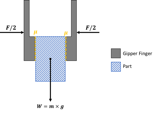
The robotic gripper must withstand not only the weight of the object but also the acceleration and the motion that is caused due to frequent movement of the object.
Free Body diagrams drawn on a sheet of paper are adequate for analyzing pairs of force components

F --> Force required to grip the object
u --> Coefficient of friction between the finger and the object
m --> object mass
g --> gravitational acceleration
Once the force acting upon the part has been estimated, it is possible to determine the required gripping force. This will depend on the coefficient of friction between the gripper and the part, and on how well the gripper can enclose or entrap the part
Stage 2: Determine additional requirements, not directly related to the act of acquiring and gripping parts
environmental requirements for example
Stage 3: Determine Specific Solutions to the requirements in stage 1 and 2
The idea here is to develop independent solutions to the individual design requirements
Stage 4: Begin to develop designs combining the foregoing modular solutions
Go through complete design cycle while combining the independent solutions into a single solution
Stage 5: Redesign the part and/or the task
At this stage it should be possible to see how changes in the part or in the robot task could simplify the design of the gripper and improve the ability of the robot to accomplish the task
Conclusion
In this part we have introduced the gripper system including architecture, main functions along with a design guide to help engineers designing their own custom grippers.


Thanks for sharing knowledge 😊 could you please share a 3D model of gripper?